| dc.description.abstract | The demand for renewable energy sources has increased significantly in recent years due to
the growing concerns about climate change and environmental sustainability. Solar energy
has emerged as one of the most promising and widely used renewable energy sources.
However, the efficiency and output of solar energy systems depend on various factors,
including the position of the sun, the angle of the solar panel, and weather conditions.
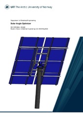
A detailed design, method, and tested outcomes of a solar angle optimizer are presented in
this master's thesis being the main focus. The primary accomplishment is the testing,
simplification, and preparation of extensive documentation that can be used in future study
on Photovoltaic system optimization. For this specificity, calculating the sun’s position using
an RTC module and positioning the PV panel perpendicular to the sun is not accomplished in
this study.
As this thesis is the improvement of a previous master’s thesis, some tests are done on
prebuilt H Bridge-motor drive, Power measuring board and Programmable Logic Controller
(PLC) codes. Moreover, all the flaws of previous designs and works are mitigated by designing
and building new boards or some other alternative ways. All the sensors and equipment are
connected to PLC and few PLC programs are developed for various tasks and tests.
Mainly, the code is developed for a motor control system that positions the Photovoltaic (PV)
panel to an optimal position where the power output is maximum. And after optimization, in
a certain interval, it positions itself accordingly, if the position of maximum output changes.
While building the whole system some safety issues are taken into consideration like storm
and uncontrolled rotation of the rig. Codes are developed to prevent uncontrolled rotation
and during storm the panels will be positioned horizontally to reduce air drag.
Several tests have been performed: The H bridge motor drive from previous work is tested
but unfortunately it was not working so a new one is designed and built.
Power measuring board from previous work is tested and there were major design flaws. As
there is limitation of time so some prebuilt devices are used to measure voltage and current
of the PV panel, instead of making a new one.
Induction sensors has been tested if they can prevent the rig from hitting any obstacles. The
‘Positional initialization of the PV panels using Induction sensors’ is also tested.
Using a strong light source at UiT Electrical Machine lab, the performance of the whole system
is observed at different conditions and the results are logged into PLC using a data logger
program.
The lab tests were performed using only one PV panel for simplification, whereas in the final
phase, it is effective for total 8 panels. With an open circuit voltage of 21.20 V and a peak
power current of 2.94 A, each panel is capable of delivering 50 Watts of peak output | en_US |


 English
 norsk
norsk
